Energy Manager
- Knowledge Base
- Function Blocks
- Energy Manager
This block can be used to determine the surplus energy and to switch loads on or off according to priority. Loads can be controlled digitally or analog.
Analog controlled loads are limited in their power between the switch-on power and their maximum rated power.
If an energy storage is used and its state of charge is below the minimum state of charge, the necessary power for the storage is given the highest priority.
Table of Contents
Inputs↑
| Abbreviation | Summary | Description | Unit | Value Range |
|---|---|---|---|---|
| Gpwr | Grid power | Negative value when delivering power to the grid. | kW | ∞ |
| Ppwr | Production power | Only used for the user interface. | kW | ∞ |
| Spwr | Energy storage power | Negative value when charging the storage. | kW | ∞ |
| Soc | Energy storage state of charge | % | 0...100 | |
| Prio | Priority selection | Starts the selected load immediately. | - | 0...12 |
| Recalc | Recalculate | Triggers a recalculation immediately. | - | 0/1 |
| L1-12 | Load 1-12 status | Current status (digital) or consumption power (analog) of the load. | - | ∞ |
| Off | Off | Pulse: Outputs are reset / switched off. On: Block is locked. Dominating input. The name of the connected sensor is used in the user interface. | - | 0/1 |
Outputs↑
| Abbreviation | Summary | Description | Unit | Value Range |
|---|---|---|---|---|
| Next | Next Calculation | Seconds until next recalculation. | s | ∞ |
| L1-12 | Load 1-12 | Output for load 1-12. Digital = 0/1. Analog = kW | - | ∞ |
| MinSoc | Minimum state of charge | Current set MinSoc. | % | 0...∞ |
| AC | API Connector | Intelligent API based connector. | - | - |
Parameters↑
| Abbreviation | Summary | Description | Unit | Value Range | Default Value |
|---|---|---|---|---|---|
| O | Offset grid power | Offset the target power value of the Energy Management. | kW | ∞ | 0 |
| MinSoc | Minimum state of charge | If value is greater than 0, charging the energy storage has the highest priority until the minimum state of charge (SoC) is reached. After that, the energy storage is only charged if there is surplus energy. | % | 0...100 | 0 |
| MaxSpwr | Maximum energy storage power | Defines the maximum charging power of the energy storage. | kW | 0...∞ | 0 |
Properties↑
| Summary | Description | Default Value |
|---|---|---|
| Properties | Edit energy manager | - |
Functionality↑
Priorities are assigned to the connected loads (1: high, 12: low). If the input (Gpwr) in combination with (Spwr) is indicating available surplus energy, the energy manager will switch as many loads on as possible, starting with the highest priority.
Loads will switch on when there is more surplus energy than the defined switch-on power for that load. Analog loads (e.g. Wallbox) will regulate the output value between switch-on power and the defined rated power.
Digital Loads where the switch-on power is greater than or equal to the rated power will be switched off again, when the surplus energy is below the rated power of the load.
Digital Loads where the switch-on power is less than the rated power will be switched off again, when the imported grid power exceeds the difference between switch-on and rated power. This can be used for loads where it is acceptable that power is imported from the grid or drawn from the energy storage.
Analog loads will be switched off again when there the available surplus energy is below the Switch-on power.
The Load status inputs (L1-L12) can be used to inform the Energy Manager about the actual status (digital) or power usage (analog [kW]) of the load.
When nothing is connected to the status input of a load, the Energy Manager assumes that the load is on when activated and exactly uses the power set on the output (analog loads) or defined by Max. Power (digital loads).
If the State of charge of the Energy storage (Soc) is below the defined Minimum (MinSoc), the Energy Manager will make it the highest priority to charge the storage with the defined power (MaxSpwr) until (MinSoc) is reached.
The Energy Manager ensures the output meets the defined Min run-time/day. If the Min run-time/day until... has already elapsed on the first activation, the output switches on immediately. At the next daily cycle, the output will be activated correctly during the specified time window.
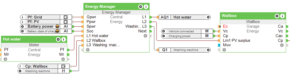
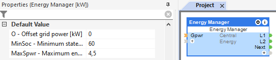
Programming example↑
In the properties window, the minimum state of charge and the maximum energy storage power can be defined.
Double click on the block to open the configuration window, here the preparation time, minimum run-time, switch-on power and the rated power of the loads must be specified:
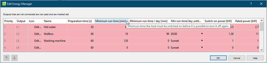
The loads are added from top to bottom when the surplus reaches the respective switch-on power.
By using the status inputs, analog controlled loads can be handled better, as these are only supplied with the required power.
The loads are switched off again in reverse order.
If a daily minimum run-time has been defined and not reached, loads are activated even without a current energy surplus in order to reach the minimum run-time/day by the defined time.